Modeling Bone Mechanics
Comparing computational and experimental mechanics of bone under load
Ideal predictions vs. simulations vs. reality
I modeled the mechanical behavior of rat femurs under three‑point bending to examine how stress, strain, and deformation distribute through bone and how well computational predictions match experimental behavior. Using ANSYS, I built and refined a finite element (FE) model with defined geometry, boundary conditions, material assumptions, and mesh refinement, generating stress, strain, and deformation maps to identify peak loading regions.
I then compared the model’s predictions to experimental force–displacement data and Digital Image Correlation (DIC) derived strain maps. The FE model showed idealized linear behavior, while experimental results reflected real‑world variability from contact mechanics, material heterogeneity, and measurement noise, highlighting both the value of FE modeling and the importance of realistic assumptions in biomechanical analysis.
First, I built a finite element model of a rat femur in ANSYS to simulate three-point bending under controlled displacement. This included defining geometry, boundary conditions, and material assumptions, generating and refining the mesh, and running sensitivity checks to ensure solution stability. The model produced full-field maps of stress, strain, and deformation, enabling identification of peak loading regions and expected bending behavior under idealized conditions.
The Setup
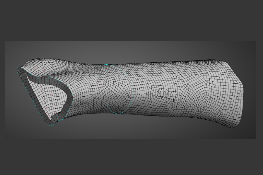
Rat femur mesh created in ANSYS.
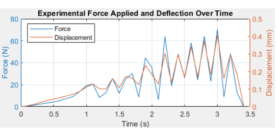
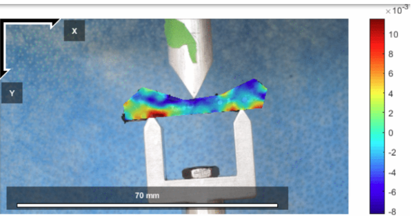
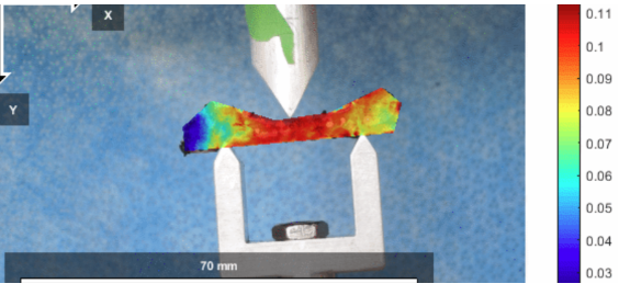
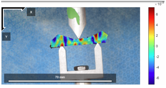
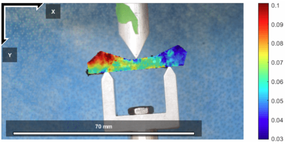
To validate the model, I executed a three-point bending experiment using a mechanical testing system with a controlled actuator and load cell. The femur was mounted on frictionless supports with a central loading point, and I prepared the surface with a speckle pattern to enable DIC for full-field strain and displacement tracking. Force–displacement data were recorded alongside synchronized video to capture deformation, allowing direct spatial comparison between experimental measurements and FE predictions.
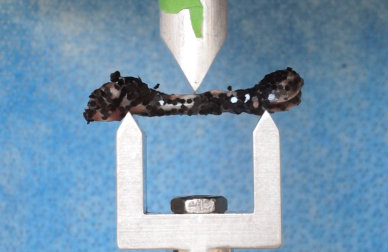
Three point bending test. The femur is coated in glitter to provide reference points for visual mapping of position changes.
Results
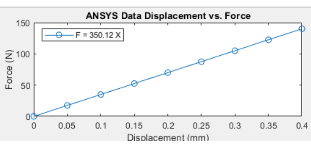
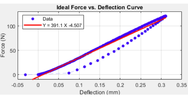
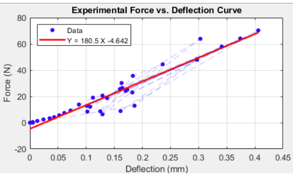
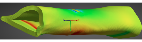
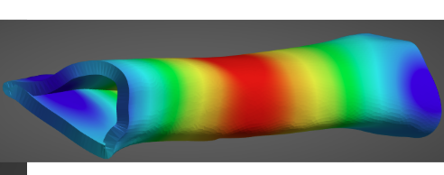
The FE model produced smooth, linear force–displacement behavior with symmetric stress, strain, and deformation gradients centered at the load site, while experimental (E) results showed the same overall trends with added variability from real-world effects. Peak stresses and strains localized near the loading point in both cases, and full-field displacement patterns closely matched the predicted bending profile. Discrepancies in stiffness and strength highlighted the impact of material heterogeneity, contact mechanics, and experimental noise, reinforcing the value of FE modeling for trend prediction and the importance of experimental validation for real biological systems.